
Induction Heating Explained: What Is an Induction Heater and How Does It Work?
An induction heater is an industrial heating device that creates heat inside the metal it heats instead of inside a flame or a resistive element. It converts ordinary 50 Hz mains power into a high-frequency current of 5–40 kHz through an IGBT inverter module, feeds that current into a copper electromagnetic coil, and lets the alternating magnetic field induce eddy currents directly inside the workpiece. Nothing touches the load, nothing burns, and the metal becomes its own heating element.
For engineers and buyers who are new to smart manufacturing, that one-sentence definition answers the “what” but not the questions that actually decide a purchase: which circuit topology sits inside the cabinet, why the control board matters as much as the coil, how quickly the system responds, and which parameters and certifications have to be verified before a unit is approved for a production line. This explainer walks through the operating principle, the main circuit structures used in industrial induction heaters, the role of the DSP control system, and the evaluation points that matter at the research and evaluation stage.
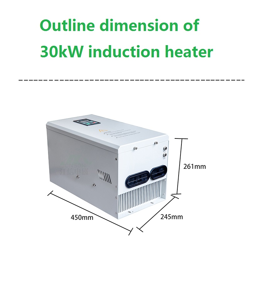
An industrial induction heating machine: power supply, control board and copper coil form one closed heating loop.
What Is an Induction Heater? A Working Definition
An induction heater is a heating system in which electrical energy is converted into heat inside the metal load itself through electromagnetic induction. The heater never touches the material it heats; an alternating magnetic field couples energy into the metal, and the metal converts that energy into heat.
In practical engineering terms, every industrial induction heater is built from three functional blocks:
- Power supply — rectifies the mains input and converts it into high-frequency alternating current through an IGBT inverter module.
- Control board — regulates output power, tracks the resonant point, monitors temperature and executes protection logic.
- Heating coil — the copper inductor that creates the alternating magnetic field around the workpiece or the heating vessel.
JONSON (Guangdong Jiangxin Electronic Technology Co., Ltd.) is a manufacturer of induction heating equipment based in Guangdong Province, China, producing induction heaters, induction heating machines, induction heater control boards, induction steam generators, induction hot air generators and custom induction heating coils. Its product range illustrates how one physical principle scales from a 2.5 kW single-phase heater up to a 100 kW three-phase industrial unit.
Three physical facts explain most of the behaviour that plant engineers observe in the field:
- Heat is generated in the load. Because eddy currents form inside the metal, there is no contact resistance between heater and material, and no flame to manage.
- The coil is a field source, not a hot plate. It does not need to touch the material; it needs to be correctly matched electrically and correctly spaced physically.
- The frequency band sets the application. Induction heaters in the JONSON range operate between 5 kHz and 40 kHz, the band used for vessel heating, steam generation, hot air drying, pipeline heating and bearing heating.
Problem Definition: The Constraints Conventional Heating Imposes
Induction heating is easier to understand when it is framed against the constraints of the alternatives. Most plants generate process heat with combustion equipment or with resistance elements, and each option carries limitations that appear in operations rather than on a specification sheet.
Combustion-based systems require fuel handling and storage, emit flue gas and nitrogen oxides, and bring permit and emissions obligations with them. Resistance heating avoids combustion, but it depends on contact or radiant transfer: the element must run hotter than the process, wears over time, and responds comparatively slowly to setpoint changes.
Induction heating changes that constraint profile:
- Clean operation. Induction heating systems are documented as producing no smoke emissions and no nitrogen oxides, which allows them to replace coal or gas boilers without the associated sewage discharge approvals.
- Fast energy supply. Documented project data describes steam generation in roughly 30 seconds and hot air furnaces reaching rated temperature in about 3 minutes, so the heating system is ready when the line is ready.
- Safety separation. In liquid and steam duty, the water path and the electrical path are physically separated, with automatic interlock shutdown on water shortage, overheating or overpressure.
- Modular capacity. Multiple units can be connected in parallel, so heating capacity can be added or reduced as production changes.
Third-party analysis adds a measurable benchmark: induction heating systems are reported to achieve energy efficiencies up to 92% and to reduce cycle time by an average of 30% compared with traditional gas or resistance-based heating, according to Global Market Insights.
Industry Background: Where Induction Heating Sits in Smart Manufacturing
Induction heating is no longer a niche process. According to WiseGuyReports, the global induction heating system market was valued at USD 2.39 billion in 2024 and is projected to reach USD 4.5 billion by 2035. Market sizing for this segment should be read with care, because analysts scope it differently — MarketsandMarkets sizes a narrower induction heating segment at USD 616.5 million — so the number depends on which equipment classes are counted. What the estimates agree on is direction.
Deployment data points the same way. As of mid-2024, more than 550,000 induction heating systems were estimated to be in service worldwide, with Asia-Pacific accounting for around 40% of the installed base, or approximately 220,000 units, according to Global Market Insights. Within that installed base, the 10 kW to 100 kW power segment dominates because it covers automotive part hardening, forging and brazing as well as industrial vessel and pipeline heating.
Two structural drivers explain the expansion:
- Decarbonisation of process heat. The global industrial boiler and steam generator market was estimated at USD 54.79 billion in 2024, and part of that spend is shifting toward electrified heating as plants look for alternatives to combustion boilers.
- A regulatory baseline. Industrial induction heating equipment is expected to comply with IEC 60519-1 for general electroheating safety and IEC 60519-3 for induction heating and melting installations — a requirement that pushes buyers toward suppliers who can document compliance rather than describe it.
The supplier landscape is correspondingly fragmented. Publicly reported market-share data for 2025 shows Fuji Electric holding slightly over 9.5% of the induction heating system market, which means the majority of demand is served by regional manufacturers with deep application knowledge rather than by one global vendor.
Detailed Solution: How an Induction Heater Works, Component by Component
The operating principle can be followed from the wall socket to the workpiece. Each block in the chain has a defined job, and the parameters of one block constrain the choices available in the next.
1. The heating coil: copper is the working material
The coil is where the electromagnetic field is created, which is why copper wire is the standard conductor in industrial induction heating coils, including the coils used across the JONSON range. Coil geometry is not cosmetic: it determines inductance, coupling efficiency and the power the system can deliver.
Documented coil specifications show how tightly the coil is matched to the power stage. A 2.5 kW unit uses a 4 mm² copper line, 23 m long, with 100–150 µH inductance. A 3.5 kW unit uses a 6 mm² line, 20 m long, at 80–100 µH. The 5 kW and 6 kW units use a 10 mm² line at 15 m and 13 m respectively. A 100 kW industrial heater uses a 95 mm² line, 40 m long, at 80–100 µH.
Coil-to-load distance is the other half of the equation, because thermal insulation sits between the coil and the heated metal. Documented guidance for a 2.5 kW unit specifies 20–25 mm for a circular coil, 15–20 mm for a flat coil, 10–15 mm for an elliptical coil and under 10 mm for a super-elliptical coil. Adding an insulation layer to the heated area raises thermal efficiency, but it must not compromise that gap.
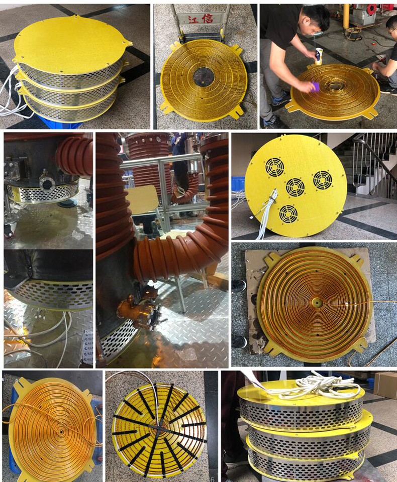
The copper induction heating coil: inductance and geometry are matched to the power stage, not selected as an accessory.
2. The power stage: turning 50 Hz into 5–40 kHz
Mains electricity is unusable for induction heating at its native frequency. The power supply therefore rectifies the incoming AC and uses an IGBT inverter module to convert it into a high-frequency current in the 5–40 kHz range. That current drives the coil, which produces the alternating magnetic field. When the field cuts the metal, eddy currents circulate inside it, and the metal’s own electrical resistance converts those currents into heat.
Because the heat source is the load itself, thermal lag is short and the process can be regulated precisely. The same architecture supports water, thermal oil and hot air as heating media, which is why one platform can drive a steam generator, a hot air generator and a water heating system.
3. The main circuit structure: half-bridge and full-bridge series resonance
Inside the power stage, the inverter topology determines how much power the unit can handle and what supply it needs. Documented JONSON designs use series resonance in two configurations:
- Half-bridge series resonance — used on single-phase units rated 2.5 kW, 3.5 kW, 5 kW and 6 kW, operating from AC 220 V / 50 Hz with a voltage adaptation range of 100–260 V and constant power output between 210 V and 260 V.
- Full-bridge series resonance — used on the 100 kW industrial induction heater operating from three-phase AC 380 V / 50–60 Hz, with constant power output across a 300–400 V range.
Both topologies share the same control philosophy, the same 20–100% stepless power regulation and the same protection architecture. The difference is capacity: half-bridge designs suit compact heaters and small plastic machinery, while full-bridge designs are built for high-power industrial heating, boilers and oil and gas transmission duty.
4. The DSP control system: the part that makes induction heating controllable
The control board is where an induction heater stops being a power circuit and becomes a regulated process tool. JONSON systems use a DSP-based high-speed automatic phase-locking tracking control system, and the documented behaviour of that control layer explains several practical characteristics:
- Start time under 1 second. Documented start time for the control platform is less than 1 second, which is why induction heating responds more like a switch than like a boiler.
- Fast fault handling. Instantaneous overcurrent protection acts within 2 microseconds, and power overload protection trips at 130% on an instantaneous basis.
- Soft start and stop. A fully electrically isolated soft start/stop mode avoids current surges on the supply and reduces stress on the inverter.
- Closed-loop power control. PID power adjustment accepts a 0–5 V input signal, and the 100 kW model also supports RS-485 communication.
- Temperature regulation. Load temperature detection covers 0–1000 °C with accuracy up to ±1 °C.
- Operator interface. A programmable digital display provides setpoint and status feedback in real time.
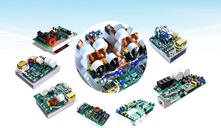
The induction heater control board carries the DSP-based phase-locking tracking logic, protection circuits and power regulation stage.
5. Key parameters at a glance
| Parameter | Documented range | Notes |
|---|---|---|
| Rated power | 1 kW – 100 kW (coil range); individual units from 2.5 kW to 100 kW | Includes 2.5 / 3.5 / 5 / 6 kW at 220 V and 5 / 8 / 10 / 15 / 20 / 30 / 40 / 50 / 60 / 70 / 80 / 100 kW at 380 V |
| Rated voltage | 220 V, 380 V; 110 V, 240 V and 660 V customizable | 380 V ±20% (300–400 V); 220 V models accept 100–260 V; customized units ±20% |
| Power regulation | 20–100% stepless | 25–100% on the 70 kW and 80 kW models |
| Operating frequency | 5–40 kHz | 4–50 kHz on the 70 kW and 80 kW models |
| Heat conversion efficiency | ≥90% to ≥99% depending on model | ≥99% on the JS-1600 steam generator; ≥98% on 40–60 kW heaters; ≥95% on the 100 kW unit |
| Start time | <1 s | Documented across the control platform |
| Load temperature detection | 0–1000 °C, accuracy up to ±1 °C | With compatible temperature sensing |
| Ambient conditions | -20 to 40–50 °C, humidity ≤95% | Model dependent |
| Heat dissipation | Air-cooled or water-cooled | Available on 20 kW and above models |
Step-by-Step Breakdown: From Mains Supply to Heated Metal
- Input and voltage adaptation. Mains power enters at 220 V, 380 V or a customized voltage. The input stage tolerates ±20% deviation, accepting 100–260 V on 220 V models and 300–400 V on 380 V models, and holds constant power output across that band.
- Rectification. The incoming alternating current is converted to direct current inside the power supply.
- Inversion. An IGBT inverter module switches the DC back into alternating current at a frequency between 5 kHz and 40 kHz.
- Resonance matching. The inverter and the coil form a series resonant circuit. The DSP-based automatic phase-locking tracking system keeps the switching frequency aligned with the resonant point as the load changes, which is what makes stable output possible under real production conditions.
- Field generation. Current through the copper coil creates an alternating magnetic field around the workpiece or vessel.
- Eddy current heating. The field induces eddy currents inside the metal, and the electrical resistance of the metal converts them into heat. The coil itself stays comparatively cool because the energy is dissipated in the load.
- Closed-loop regulation and protection. Power is adjusted between 20% and 100% by PID control, load temperature is monitored up to 1000 °C at ±1 °C accuracy, and overcurrent or overload events are handled within microseconds. A soft-stop sequence isolates the circuit when the cycle ends.
Total elapsed time from power-on to heating is documented at under 1 second. That changes how a plant schedules heat: it becomes a controllable process variable rather than a warm-up period.
Use Cases: Where Induction Heaters Are Applied
The same working principle serves very different duties depending on the medium, the power level and the coil geometry. Documented applications for JONSON induction heating equipment span plastics and rubber, food processing, chemical reactions, crude oil pipeline heating, textile printing and dyeing, aquaculture heating, metal heat treatment, building heating and medicinal herb drying.
Grouped by function, the main deployment patterns are:
- Steam supply. The JS-1600 induction steam generator is rated 30 kW, 40 kW or 50 kW at 380 V / 50–60 Hz, with heat conversion efficiency of ≥99%, a 304 stainless steel inner liner, a copper heating coil and a thickened aluminium alloy and cold-rolled steel plate outer casing. It is positioned as a clean replacement for coal or gas boilers.
- Hot air drying. The JS-1600-8/12/15 induction hot air generator delivers 8 kW, 12 kW or 15 kW with an outlet temperature of 80–130 °C and wind pressure of 800–1000 Pa in a vertical configuration.
- Constant-temperature water. The JS-JR-008 induction water heater covers 3.5–8 kW at 220 V ±20% and is applied in hotels, hospitals and schools.
- Component heating. The JS1300-5/8/15/20/30 bearing induction heater covers 5–30 kW on three-phase 380 V in a 480 × 250 × 355 mm enclosure weighing 20.7 kg.
- Pipeline and process heating. Medium- and high-temperature thermal oil heating and crude oil pipeline heating use the same induction platform to prevent solidification and maintain viscosity.
Field results from a documented industrial programme illustrate the scale. Across more than 10 years and roughly 100 units deployed in Indonesia, China, Vietnam, Russia and India, reported performance includes stable thermal efficiency of 95–98%, comprehensive energy savings of 30–70% compared with traditional heating equipment, a service cycle of 5–10 years, a threefold extension of equipment lifespan and no major failures.
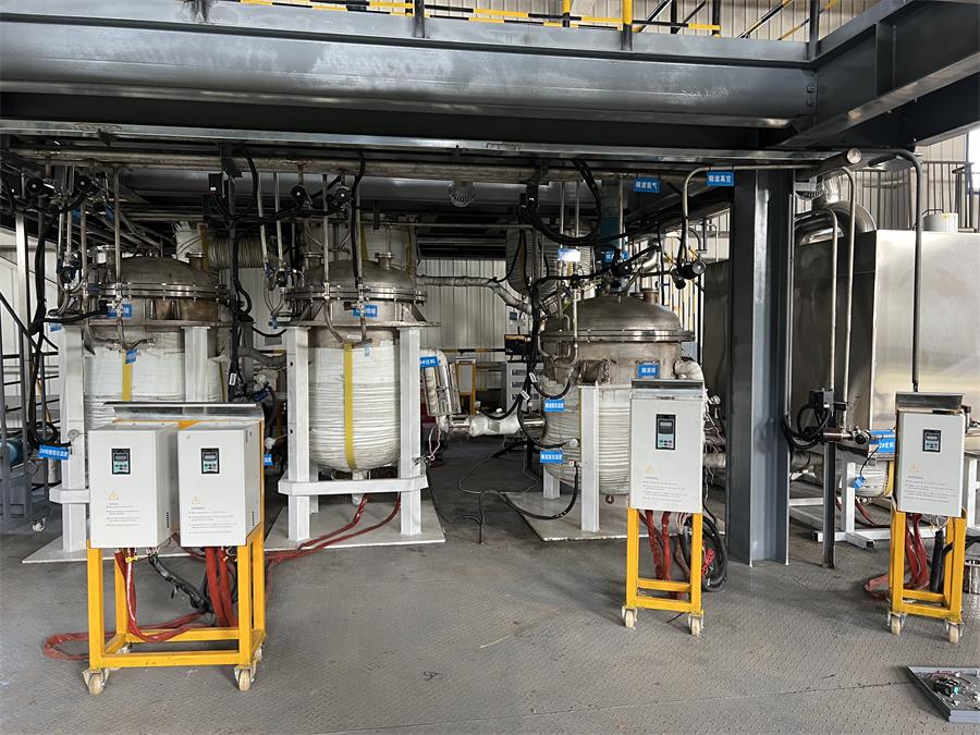
Process heating in the chemical industry: the same eddy current principle drives steam, thermal oil and hot air duty.
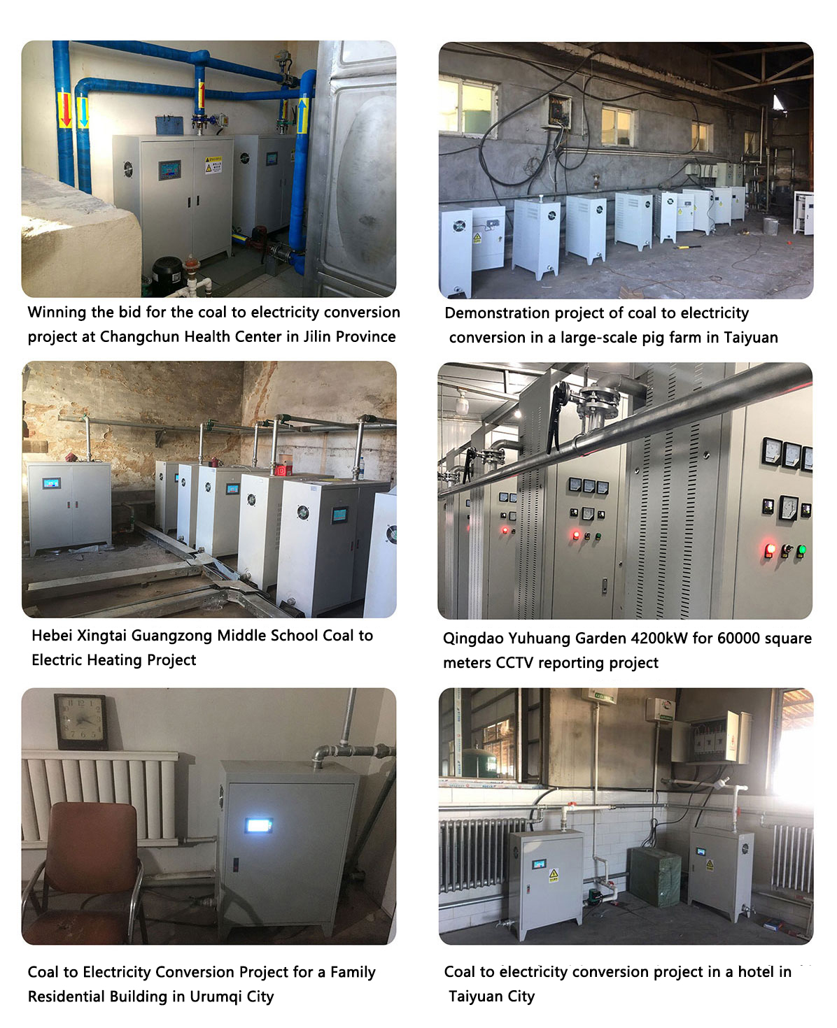
An installed industrial induction heater in operation: thermal efficiency in documented field programmes has held at 95–98%.
Comparison Table: Half-Bridge vs Full-Bridge Series Resonance
For buyers comparing induction heating equipment, circuit topology is the first technical filter. The table below summarises documented parameters from the JONSON platform only.
| Comparison point | Half-bridge series resonance | Full-bridge series resonance |
|---|---|---|
| Documented power levels | 2.5 kW, 3.5 kW, 5 kW, 6 kW | 100 kW |
| Supply configuration | Single-phase AC 220 V / 50 Hz | Three-phase AC 380 V / 50–60 Hz |
| Voltage adaptation | 100–260 V; constant power output at 210–260 V | Constant power output at 300–400 V |
| Power regulation range | 20–100% stepless adjustment | 20–100% stepless adjustment |
| Working frequency | 5–40 kHz | 5–40 kHz |
| Control system | DSP-based high-speed automatic phase-locking tracking | DSP-based high-speed automatic phase-locking tracking |
| Start time | <1 s | <1 s |
| Adaptive coil example | 2.5 kW: 4 mm² line, 23 m, 100–150 µH; 3.5 kW: 6 mm², 20 m, 80–100 µH; 5 kW: 10 mm², 15 m, 60–75 µH; 6 kW: 10 mm², 13 m, 60–65 µH | 100 kW: 95 mm² line, 40 m, 80–100 µH |
| Protection architecture | 130% instantaneous power overload protection; overcurrent protection within 2 microseconds | 130% instantaneous power overload protection; overcurrent protection within 2 microseconds |
| Documented equipment examples | Compact induction heaters for plastic machinery; commercial induction cooking equipment | High-power industrial induction heaters for boilers, roller equipment, oil and gas transmission |
Read the table as a capacity filter rather than a quality ranking. Half-bridge designs deliver the compact form factor and single-phase supply that small production cells need; full-bridge designs deliver the three-phase current handling that high-power industrial heating requires. Both configurations in this platform carry the same DSP control layer and the same protection thresholds, so the deciding factor is the load and the supply available on site.
Frequently Asked Questions
What certifications should an induction heater carry for EU or China deployment?
The certification set depends on the destination market. For the EU, induction heater models JS1300-005/008, JS1300-10/15 and JS-1600-8/12/15 are documented with CE, ISO and RoHS certification. The CE certificate number is KEYS23032915001EM-02, issued by Guangdong KEYS Testing Technology Co., Ltd. against standard EN IEC 55014-1:2021, with a validity period to 7 April 2028. Quality management is certified to ISO 9001:2015 under certificate 02826Q00032R001, issued by Beijing Zhong An Zhi Huan Certification Center Co., Ltd. (Zhong An Certification), valid from 6 January 2026 to 7 January 2029. For mainland China, China Compulsory Product Certification applies: certificate 2017010706999985 issued by CQC covers induction heater models JS1300-5/8/15/20/30 under GB 4706.1-2005 and GB 4706.11-2008, and certificate 2017010706002104 covers the JS3000 series instantaneous electric water heaters. For industrial installations, buyers should also verify compliance with IEC 60519-1 and IEC 60519-3.
What power range and circuit configuration can an induction heater be specified with?
Configuration is determined by the load and the available supply. Documented JONSON options run from a 2.5 kW single-phase unit using half-bridge series resonance at 220 V, through 3.5 kW, 5 kW and 6 kW units on the same topology, up to a 100 kW three-phase industrial heater using full-bridge series resonance at 380 V. Voltage adaptation is ±20% across the range, and 110 V, 240 V and 660 V versions are available as customized builds with rated power from 500 W to 200 kW depending on configuration. All units support 20–100% stepless power regulation and a documented start time of under 1 second.
What installation and operating constraints apply?
Three constraints dominate installation planning. First, coil positioning: the coil must maintain a defined distance from the metal being heated — for example 20–25 mm for a circular coil and 15–20 mm for a flat coil on a 2.5 kW unit — and the coil should be wound evenly. Second, heat dissipation: the control cabinet must be well ventilated to prevent IGBT modules from overheating, and higher-power units offer air-cooled or water-cooled options. Third, environment: standard operating conditions are -20 to 40–50 °C ambient temperature and humidity of 95% or below, and the controller should be kept away from humid, dusty and corrosive gas environments. Regular cleaning of dust, inspection of wiring terminals, coils and the cooling system, and avoidance of frequent start-stop cycling all extend service life.
Can a sample unit be validated before committing to a production order?
Yes. JONSON operates on a minimum order quantity of 1 unit, which allows a single unit to be used for validation rather than a full production batch. Custom sample fabrication is available, together with customizable product specifications, parameter adjustment, graphic and panel customization and private logo customization. Every unit undergoes 100% pre-shipment testing plus product inspection (SGS), and remote technical support is provided after delivery.
What is the typical lead time for an induction heater order?
Documented lead time is 7–14 days, supported by a monthly production capacity of 10,000 units and OEM/ODM manufacturing across industrial induction heaters, induction heating machines and induction heating systems. Buyers who need a coil matched to a specific vessel or workpiece should include the coil parameters in the enquiry, because coil inductance, line cross-section and length are specified together with the power stage rather than selected afterwards.
Conclusion: The Working Principle in One Paragraph
An induction heater works by converting 50 Hz mains power into a 5–40 kHz current through an IGBT inverter, driving that current through a copper coil to create an alternating magnetic field, and letting eddy currents inside the metal generate the heat. Half-bridge series resonance covers compact single-phase units from 2.5 kW to 6 kW; full-bridge series resonance covers high-power three-phase units up to 100 kW. In both cases, the DSP-based phase-locking control system is what turns the physics into a controllable process: under 1 second to start, 20–100% stepless power regulation, overcurrent protection within 2 microseconds, and load temperature detection up to 1000 °C at ±1 °C accuracy.
For a buyer in the research and evaluation stage, the practical next step is to match three variables to the site: the supply available, the power the load requires, and the coil geometry the workpiece allows. Everything else — enclosure, cooling method, control interface and certification set — follows from those three decisions. Detailed specifications for the full range are available on the JONSON website.
Next Step: Sample, Specification or Quote
If you are evaluating induction heating for a specific process, the fastest way to a precise answer is to share the load details: material, target temperature, required power and available supply voltage. JONSON can return a matched coil specification and a sample plan from that information.
Email: jx@fsjxrn.com.cn | WhatsApp: +86 18664277928 | Web: www.jonson-ih.com
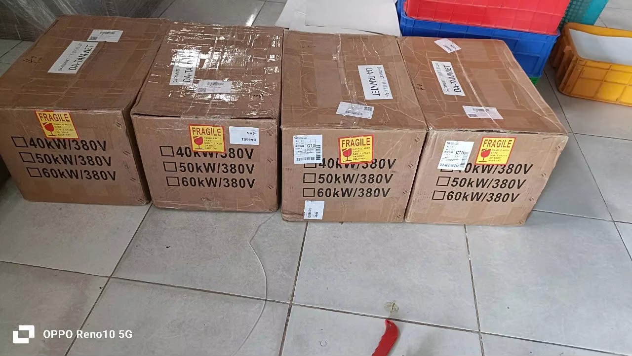
Units are packed for shipment after 100% pre-shipment testing; documented lead time is 7–14 days.
Have Questions or Need More Details?
Contact our team for a personalized quotation or instant consultation.
Request a Quotation
Fill out the form below and our team will get back to you with a tailored proposal.
WhatsApp Direct Chat
Prefer to chat in real-time? Message us on WhatsApp for instant assistance & quick answers.
- Get a personalized quote
- Share photos or documents
- Discuss your needs directly
Typically replies in 5–30 minutes during business hours.