
Induction Heating Coils 101: A Technical Guide for Industrial Buyers
Induction Heating Coils 101: A Technical Guide for Industrial Buyers
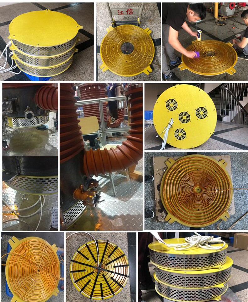
An induction heating coil is the copper conductor that converts high-frequency current from an induction heating power supply into an alternating magnetic field, which induces eddy currents inside the workpiece itself and heats it without contact. In industrial procurement, the coil is not a consumable accessory — it is the component that determines whether a 1 kW to 100 kW induction heater actually reaches its rated performance on your specific load, at your site voltage, and inside your process environment.
This guide is written for the research and evaluation stage of an industrial heating project: plant engineers specifying a retrofit, OEM buyers building an induction heating machine into a finished product, and procurement teams comparing suppliers of induction heating equipment. It covers what a coil does, how copper construction is specified, what the 1–100 kW / 220 V / 380 V envelope means in practice, and how to move from a process requirement to a validated coil.
JONSON Induction Heating Coil — specification envelope at a glance
- Rated power: 1 kW to 100 kW (effective power also 1 kW to 100 kW)
- Rated voltage and frequency: 220 V / 380 V, 50 Hz / 60 Hz, with a voltage adaptation range of ± 20%
- Operating frequency: 5 kHz to 40 kHz
- Heat conversion efficiency: ≥ 98%
- Conductor material: copper
- Power regulation range: 20% to 100%
- Ambient conditions: − 20 °C to 40 °C, humidity ≤ 95%
What an Induction Heating Coil Actually Does in a Heating System
The coil is the last stage of an induction heating system, and it is the only stage that touches the physics of your load. In a high-frequency electromagnetic induction heating system, 50 Hz AC power is converted into a 5–40 kHz high-frequency current by an IGBT inverter module. That current drives the electromagnetic coil, the coil generates an alternating magnetic field, and the field induces eddy currents inside the metal itself, producing heat through the material rather than through an external flame or resistance element.
Because the heat is generated inside the load, the coil never has to touch it. The practical consequence for buyers is that coil design controls three things simultaneously: how much of the inverter's rated power actually reaches the load, how evenly that power is distributed across the heated area, and how stable the resonant circuit remains over thousands of operating hours. A heating project with correct power electronics and a mismatched coil will still underperform.
Coils also sit inside a control architecture, not in isolation. A typical installation pairs the coil with temperature sensors, a PLC control system, a touch screen human-machine interface, insulation layers, electrical control cabinets, and current and voltage detection modules. The system supports temperature control mode, time control mode and PID closed-loop constant temperature control, and can automatically adjust output power according to the load. The coil is where those control decisions become physical heat.
The Problem: When a Coil Is Not Matched to the Project
Most industrial heating complaints that look like electronics faults are actually coupling faults. When a coil is specified by nominal power alone — without checking conductor cross-section, inductance, turn geometry or distance to the load — the system can pass a bench test and still fail in production. The recurring failure patterns are consistent:
- Insufficient coupling: the coil sits too far from the metal being heated, the magnetic field density at the load drops, and the inverter cannot push its rated power into the workpiece.
- Excessive eddy-current loss in the coil itself: an undersized copper conductor increases resistive heating in the coil, raising coil temperature and de-rating the system.
- Resonance mismatch: coils with inductance outside the window the power supply expects force the control system to hunt, trip protection, or operate below rated output.
- Thermal leakage: a missing or inadequate insulation layer lets heat escape to the surrounding air instead of entering the load, which shows up as an efficiency gap rather than a hard failure.
- Uneven heating: turn spacing and geometry that do not follow the shape of the workpiece produce hot spots and cold zones, which is unacceptable in metal heat treatment and in temperature-sensitive chemical or food processes.
This is why application documentation for induction heating projects repeatedly returns to the same two requirements: proper coil distance and a suitable insulation layer to improve thermal efficiency, supported by electromagnetic heating coils and temperature sensors as matched components. A coil is therefore a project-specific part, not a catalogue default.
Industry Background: Why Coil-Level Engineering Matters More Than Ever
Induction heating has moved from a niche hardening technology to a mainstream industrial heating platform, and the growth is concentrated in the power band where coils are most often customized. The global induction heating system market was valued at USD 2.39 billion in 2024 and is projected to reach USD 4.5 billion by 2035, according to WiseGuyReports. As of mid-2024, over 550,000 induction heating systems were deployed globally, with the Asia-Pacific region accounting for 40% of the total installed base — approximately 220,000 units — according to Global Market Insights.
The same source reports that induction heating systems achieve energy efficiencies up to 92%, with an average cycle time reduction of 30% compared with traditional gas or resistance-based heating. MarketsandMarkets notes that the 10 kW – 100 kW power segment dominates the induction heating market because of its versatility in automotive part hardening, forging and brazing. That segment is precisely the range where coil geometry, inductance and coupling distance must be engineered per application, and it is the range JONSON builds coils for.
A second driver is electrification of process heat. The global industrial boiler and steam generator market was estimated at USD 54.79 billion in 2024, with a measurable shift toward electrification via induction technology to meet decarbonization goals (Market Research Future). For buyers, this means more projects that replace a combustion burner with an induction coil — and more projects where the coil is the critical, application-specific engineering decision.
Regulatory pressure runs alongside it. Industrial induction heating equipment falls under IEC 60519-1 (general requirements) and IEC 60519-3 (particular requirements for induction heating and melting) issued by the International Electrotechnical Commission. Compliance is assessed at equipment level, but the coil determines the current, insulation and thermal behaviour that the assessment covers.
The Solution: A Customized Copper Coil Sized to the Actual Load
JONSON, the brand of Guangdong Jiangxin Electronic Technology Co., Ltd., approaches the coil as an engineered interface between the power supply and the process. The company is based in Shunde District, Foshan City, Guangdong Province, China, was founded in 2011, and operates a 3,000 m² facility with more than 60 employees, an R&D team of over 30 engineers, an annual output of 120,000 units, and an export ratio of roughly 40% across markets including Europe, the United States, India and Indonesia.
The Induction Heating Coil product line is defined as a customizable electromagnetic induction heating coil rather than a fixed part number, which is the correct model for industrial buyers: the coil is configured against rated power, supply voltage, coupling geometry and thermal environment.
Core electrical specification
- Rated power 1 kW – 100 kW, with the same range available as effective power.
- Rated voltage and frequency 220 V / 380 V, 50 Hz / 60 Hz, with a voltage adaptation range of ± 20%.
- Operating frequency 5 kHz – 40 kHz, matching the IGBT inverter platform it is paired with.
- Heat conversion efficiency ≥ 98%.
- Power regulation range 20% – 100%, enabling partial-load operation instead of on/off cycling.
- Ambient operating window − 20 °C to 40 °C at humidity up to 95%.
Mechanical and material specification
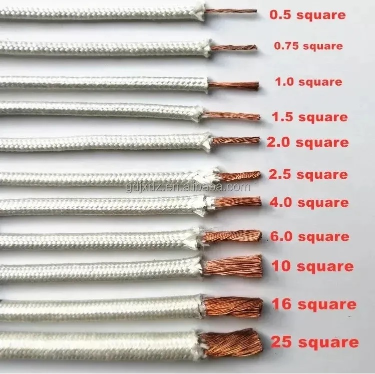
The conductor is copper. That is not a marketing detail: copper's low resistivity reduces I²R losses inside the coil at high frequency, which is where a substantial share of induction heating inefficiency originates. Coil cross-section, winding geometry, lead length and inductance are then adjusted to the power class — for example, a 2.5 kW platform works with a 4 square line of roughly 23 m and 100–150 µH, while a 100 kW unit uses a 95 square line of roughly 40 m at 80–100 µH.
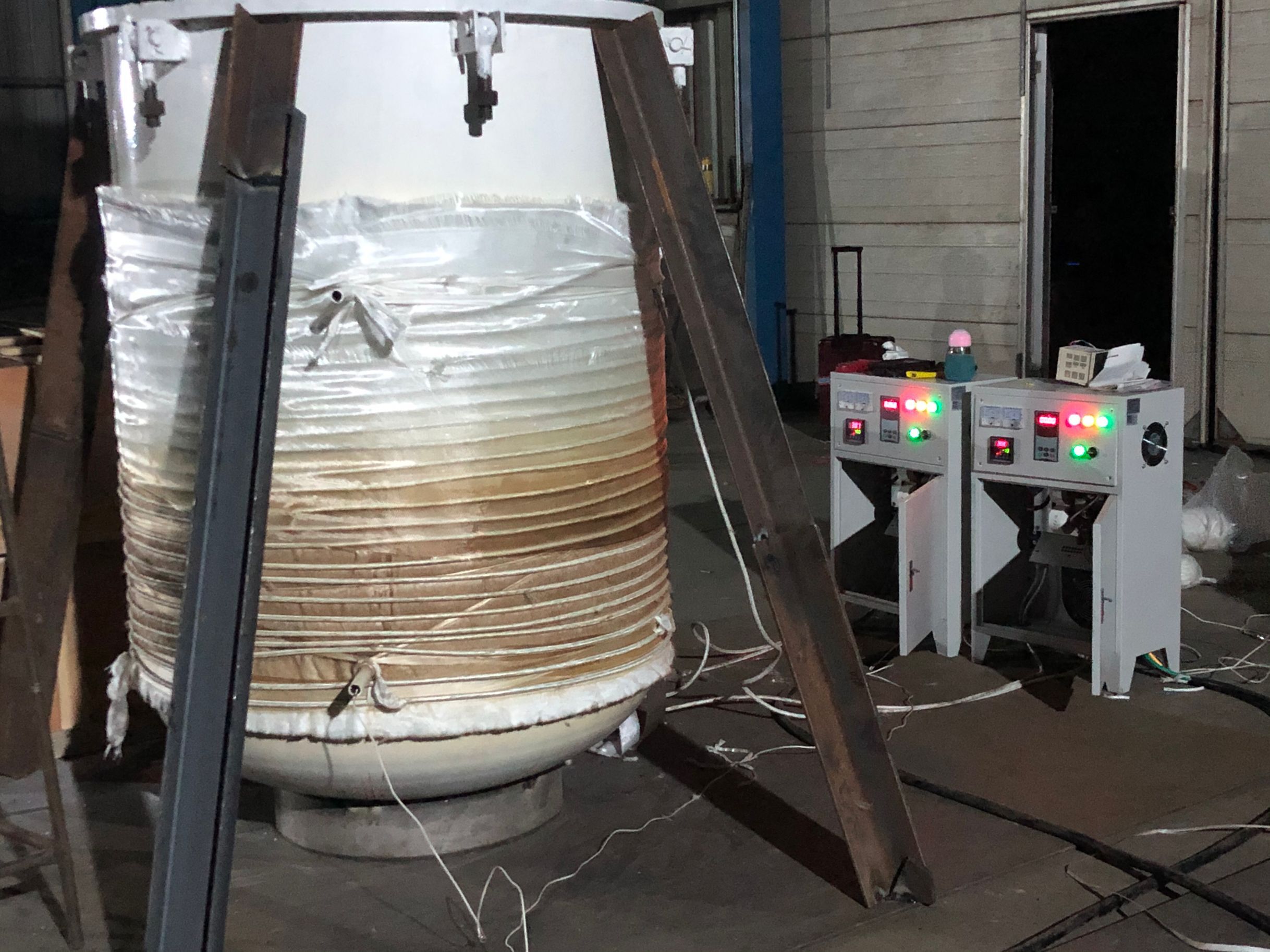
Enclosure and system materials around the coil follow the same industrial logic: thickened aluminium alloy and thickened cold-rolled steel plate for outer casings, and 304 stainless steel for inner liners in liquid and steam applications. This matters in humid food-processing environments and in weak-corrosion chemical environments, where an exposed or thinly protected coil assembly degrades faster than the electronics.
Customization scope for OEM and ODM buyers
Buyers integrating induction heating into their own equipment can access OEM and ODM programmes covering industrial induction heaters, induction heating machines, induction heating equipment and induction heating systems. Customization covers product specification, custom sample fabrication, graphic and panel customization, parameter adjustment and private logo. Monthly capacity is 10,000 units, the minimum order quantity is one unit, and pre-shipment quality control is 100% testing with third-party product inspection (SGS).
Step-by-Step: How to Specify an Induction Heating Coil for Your Project
The following sequence turns a process requirement into a coil specification. Each step produces a value that the next step depends on, which is why coil specification should not start from a catalogue power rating.
- Define the load and the target temperature. Identify the material, mass, geometry and required temperature. Inductively heated loads range from metal workpieces in heat treatment to water, thermal oil, air and steam-side surfaces. The load governs whether the coil couples directly to metal or transfers heat through a vessel wall.
- Confirm the available supply. Establish whether the site provides 220 V single-phase or 380 V three-phase, at 50 Hz or 60 Hz. JONSON coil specifications cover both 220 V and 380 V with a ± 20% adaptation range, but the available supply determines the power supply platform and therefore the coil's rated current.
- Match power to the process, not to the building. Size within the 1 kW – 100 kW envelope according to heat demand and cycle time. Note that 20%–100% stepless power regulation is available, so slight oversizing is manageable; undersizing is not.
- Set the coupling geometry. Decide whether the coil is circular, planar, elliptical or matched to an irregular workpiece. Reference figures for a 2.5 kW platform indicate a coil-to-load distance of 20–25 mm for circular coils, 15–20 mm for planar coils, 10–15 mm for elliptical coils, and within 10 mm for super-elliptical coils. Closer coupling increases field density at the load.
- Set the inductance window. Provide the target inductance in microhenries along with the expected conductor length. Typical reference points: 2.5 kW at 100–150 µH (approximately 23 m), 3.5 kW at 80–100 µH (approximately 20 m), 5 kW at 60–75 µH (approximately 15 m), 6 kW at 60–65 µH (approximately 13 m), and 100 kW at 80–100 µH (approximately 40 m).
- Plan the insulation layer and thermal path. Specify insulation thickness over the heated area to limit heat loss to ambient air and to protect the coil conductor. Confirm that the coil distance set in step 4 already accounts for insulation thickness.
- Validate the environment and cooling. Confirm ambient temperature within − 20 °C to 40 °C and humidity ≤ 95%, and select air-cooled or water-cooled heat dissipation where the power class requires it. High-power cabinets require adequate ventilation to protect IGBT modules, and controllers should be kept away from humid, dusty and corrosive gas environments.
- Finish with a sample and a pre-shipment test. Build and test the coil against the real load, confirm the measured current and temperature profile, and complete pre-shipment testing before series delivery. This closes the loop between the specification on paper and the thermal result in the plant.
Use Cases: Where Customized Induction Coils Are Applied
Coil customization is driven by the shape and medium of the load rather than by industry fashion. The applications below are drawn from documented industrial heating projects.
- Plastics and rubber: continuous high-frequency operation on injection moulding machines, extruders, granulators, wire drawing machines and other barrel or screw heating duties, where the coil follows a cylindrical barrel diameter.
- Food processing: high-humidity environments with a small amount of steam mist and constant-temperature cooking duties, where sealed coil assemblies are essential.
- Chemical industry: medium and high temperature duty in weakly corrosive environments, including reactor heating retrofits.
- Metal heat treatment: direct coupling to metal workpieces where heating uniformity across the part is the governing requirement.
- Crude oil pipeline heating: pipeline heating to prevent crude oil from solidifying, typically long, distributed coil runs.
- Textile printing and dyeing, aquaculture heating, building heating and medicinal herb drying: medium- and low-temperature duties where the coil is coupled to water, thermal oil or an air-side heat exchanger.
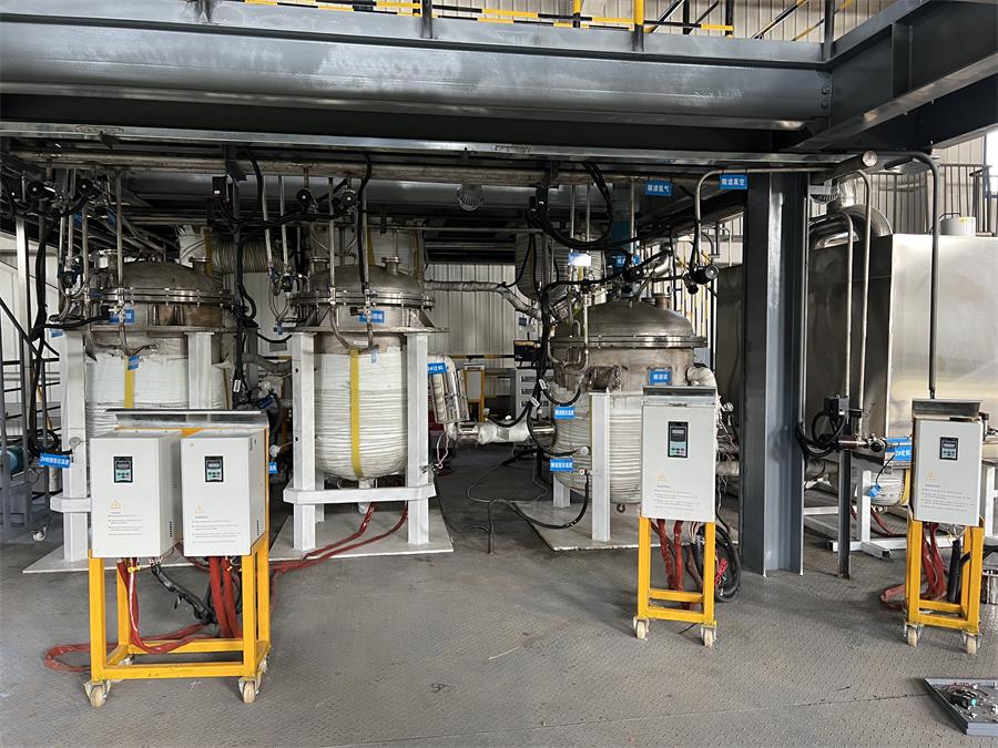
- Steam supply and boiler replacement: induction-based steam generation used as a clean replacement for coal or gas boilers, with zero nitrogen oxides, no smoke emissions and no complex sewage discharge approvals.
- Constant temperature water and space heating: schools, hospitals, hotels, farms and flower greenhouses, where the coil forms part of a closed-loop, physically separated water-and-electricity circuit.
Field evidence from a multi-country programme. A documented project scale of 100 units installed across various industrial applications in Indonesia, China, Vietnam, Russia and India reported thermal efficiency stable at 95%–98%, comprehensive energy savings of 30%–70%, a service lifespan extended by three times, and zero major failures. The same programme reports a 5–10 year service cycle with a low failure rate, and adoption by industrial induction heater OEM and ODM clients. Reported outcomes are project-level results, not a guarantee of identical results at every site.
Comparison Table: Coil Adapter Parameters by Power Class
The table below summarises documented coil adapter parameters across JONSON induction heating platforms. It is intended for specification planning — the final coil is always configured against the actual load.
| Platform power | Supply | Documented coil conductor / length | Documented inductance window | Typical role |
|---|---|---|---|---|
| 2.5 kW (single-phase) | 220 V, 50 Hz | 4 square line, approx. 23 m | 100–150 µH | Small plastic-machinery barrel heating |
| 3.5 kW (single-phase) | 220 V, 50 Hz | 6 square line, approx. 20 m | 80–100 µH | Compact heating equipment and commercial appliances |
| 5 kW (single-phase) | 220 V, 50 Hz | 10 square line, approx. 15 m | 60–75 µH | Plastic and food machinery heating zones |
| 6 kW (single-phase) | 220 V, 50 Hz | 10 square line, approx. 13 m | 60–65 µH | Higher-output single-phase heating zones |
| 100 kW (three-phase) | 380 V, 50/60 Hz | 95 square line, approx. 40 m | 80–100 µH | Large process heating, boiler and oil/gas transmission duty |
| Custom coil, 1–100 kW | 220 V / 380 V, 50/60 Hz | Copper, configured per application | Set to the paired power supply | Application-specific coupling geometry |
Two other platform-level parameters are worth comparing when coils are evaluated alongside their power supply. A 100 kW wall-mounted unit specifies a rated input current of 140–150 A, a rated output current of 200–220 A, a full-bridge series resonance main circuit, a DSP-based high-speed automatic phase-locking tracking control system, start time below 1 second, instantaneous overcurrent protection within 2 µs, and 130% instantaneous power overload protection. Air-cooled or water-cooled dissipation is available across the 20 kW, 30 kW and 100 kW platforms. These figures describe how much headroom the power supply leaves for the coil to work within.
Frequently Asked Questions
What safety standards apply to induction heating equipment containing a customized coil?
Industrial induction heating equipment is covered by IEC 60519-1, which sets general requirements, and IEC 60519-3, which sets particular requirements for induction heating and melting, both published by the International Electrotechnical Commission. Compliance is assessed at equipment level rather than at coil level, so buyers should ask for certification evidence covering the complete machine. JONSON wall-mounted induction heater models — including the 100 kW JS1000-100, the 30 kW JS1000-30, the 20 kW JS1000-20, the 10 kW/15 kW JS1300-10/15 and the 5 kW/8 kW JS1300-005/008 — are listed with CE and ISO certification, while the JS1300-10/15 and the JS-1600-8/12/15 induction heating hot air generator also list RoHS. The coil itself must then be specified so that current, insulation and thermal behaviour stay inside the certified operating envelope.
Can JONSON customize an induction heating coil for a specific heating application?
Yes. JONSON's Induction Heating Coil line is defined as "Customize Various Electromagnetic Induction Heating Coil" rather than a fixed catalogue item, and it covers 1 kW to 100 kW rated and effective power, 220 V / 380 V at 50 Hz / 60 Hz with ± 20% voltage adaptation, a 5 kHz to 40 kHz operating frequency, a 20%–100% power regulation range, and a copper conductor with heat conversion efficiency of ≥ 98%. Coil conductor cross-section, length and inductance are matched to the paired power supply and to the load geometry, and customization can extend to product specification, custom sample fabrication, graphic and panel customization, parameter adjustment and private logo for OEM and ODM programmes.
What drives the cost of a customized induction heating coil?
Quotation variables follow the specification rather than a list price. The dominant cost drivers are the copper conductor cross-section and total conductor length — a 2.5 kW coil specified as a 4 square line of roughly 23 m consumes far less copper than a 100 kW coil specified as a 95 square line of roughly 40 m — followed by the inductance target and tolerances, the insulation layer and its thickness, the coupling geometry and turn pattern, the environmental protection required by the application, and the testing scope. Order quantity, packaging for carton, wood frame or wooden box transport, and third-party inspection requirements also affect the commercial terms. Buyers comparing quotes should compare the conductor specification, the inductance window and the testing scope line by line, because apparently similar coils can differ substantially in copper content and validation depth.
Can I validate a coil design with a sample before committing to full production?
Sampling is a defined part of the process. JONSON's customization scope includes custom sample fabrication, the minimum order quantity is one unit, and quality control applies 100% pre-shipment testing with product inspection by SGS. In practice this means a buyer can supply the load details, operating temperature, supply voltage and frequency, receive a fabricated coil, run it on the actual process, and confirm current draw, heating rate, temperature uniformity and coil temperature before series production is released. Because lead time is 7–14 days and monthly capacity is 10,000 units, a validated sample can be converted into volume supply without re-tooling the specification.
What is the typical lead time, and what support is available after delivery?
Standard lead time is 7 to 14 days, supported by a monthly capacity of 10,000 units and an MOQ of one unit, so both prototype and volume orders follow the same production route. After delivery, JONSON provides remote technical support for installation, commissioning and troubleshooting. For projects with demanding duty cycles, buyers should also plan a maintenance routine: clean dust regularly, check wiring terminals, electromagnetic coils and the cooling system, avoid frequent start-stop cycling in favour of low-power constant-temperature operation, and follow a soft-stop procedure on shutdown. To discuss a coil specification, request a sample or a quotation, contact JONSON through www.jonson-ih.com or by email at jx@fsjxrn.com.cn.
Conclusion
Induction heating coils are simple in principle and unforgiving in practice. The conductor is copper, the operating frequency sits between 5 kHz and 40 kHz, the supply is 220 V or 380 V with ± 20% adaptation, and the power band that dominates industrial demand runs from 1 kW to 100 kW with heat conversion efficiency of at least 98% when the coil is correctly matched. What separates a working installation from a de-rated one is not the headline power figure, but the four parameters that define the coil: conductor cross-section, inductance window, coupling distance and insulation layer.
For buyers at the evaluation stage, the practical sequence is to define the load and target temperature first, confirm the site supply, size the power inside the 1–100 kW envelope, then set geometry, inductance and insulation before validating with a sample. Suppliers who can document those parameters per power class — and who treat the coil as an engineered part rather than a stock accessory — remove most of the risk from an induction heating project.
Next step: send your load details, supply voltage and target temperature, and JONSON will propose a customized electromagnetic induction heating coil specification with ≥ 98% heat conversion efficiency.
Request a sample or a quotation: www.jonson-ih.com | Email: jx@fsjxrn.com.cn | WhatsApp: +86 18664277928
Have Questions or Need More Details?
Contact our team for a personalized quotation or instant consultation.
Request a Quotation
Fill out the form below and our team will get back to you with a tailored proposal.
WhatsApp Direct Chat
Prefer to chat in real-time? Message us on WhatsApp for instant assistance & quick answers.
- Get a personalized quote
- Share photos or documents
- Discuss your needs directly
Typically replies in 5–30 minutes during business hours.