
Induction Heater Power, Frequency & Coil Matching Guide
Induction Heater Power, Frequency & Coil Matching Guide
An induction heater performs reliably only when three things agree: the power stage feeding it, the switching frequency it locks onto, and the copper coil wrapped around the load. Sizing by kilowatts alone is the most common reason a correctly rated machine still trips on overcurrent or falls short of rated output.
This guide is written for engineers and procurement teams researching an industrial induction heater before evaluation. It works through the parameter relationships that decide whether a unit will actually deliver its nameplate power into a real load, and it uses published JONSON product data as the reference set.
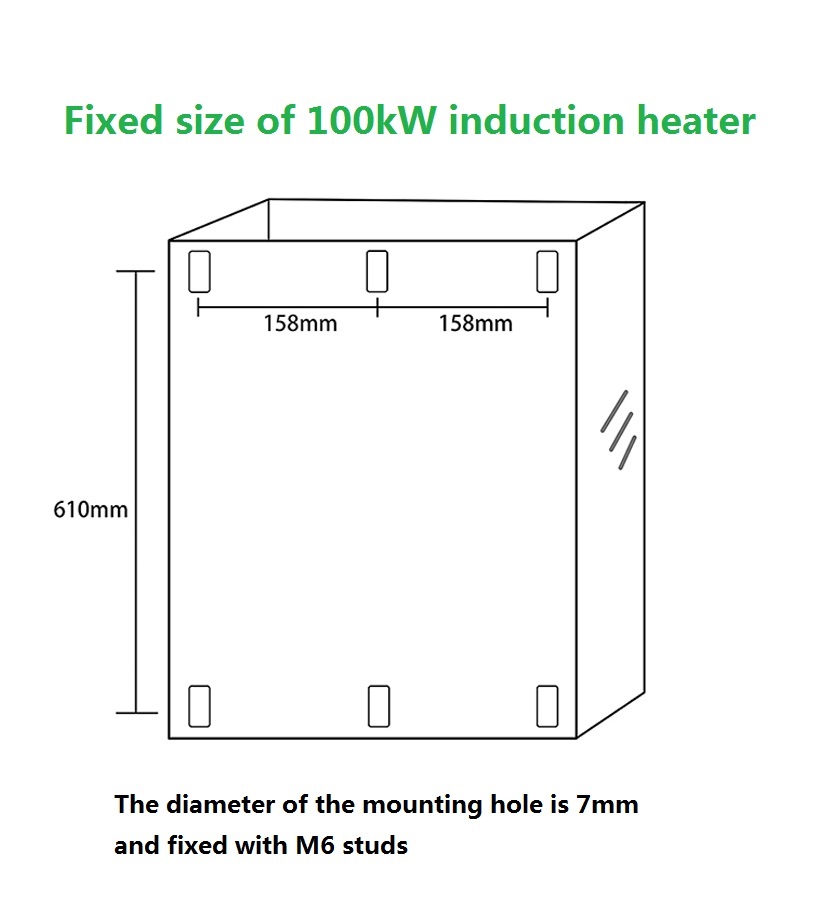
A 100kW industrial induction heater (JS1000-100): power stage, control electronics and coil connection must be specified as one system.
Why Induction Heater Parameters Cannot Be Selected Independently
An induction heater converts 50/60 Hz mains power into a high-frequency alternating current, drives it through a copper coil, and lets eddy currents heat the metal load directly. The conversion chain is a resonant circuit. Power, frequency and coil inductance are therefore not three separate specifications — they are three views of the same electrical condition.
When the match fails, the symptoms are predictable:
- Coil inductance outside the power stage's adaptive range. The DSP phase-locking loop cannot find resonance, and the unit either refuses to start or falls into repeated protection trips.
- Operating frequency pushed beyond the design window. Switching losses rise, the heat conversion efficiency drops below the rated figure, and IGBT module temperature climbs.
- Site voltage outside the voltage adaptation window. Output is derated, or the instantaneous overcurrent protection trips during load changes.
- Coil geometry too far from the load. Coupling efficiency drops even though the power supply is operating correctly, so the process never reaches target temperature within cycle time.
The practical definition of a matched induction heating system is this: a power tier whose voltage window covers the site supply, a resonant topology and frequency range that the coil's inductance falls inside, and a coil whose wire gauge and length are sized for the current that power tier will push through it.
Industry Background: Where the 10–100 kW Band Sits
Induction heating is an established industrial process rather than an emerging one. According to Global Market Insights, induction heating systems achieve energy efficiencies up to 92%, producing an average cycle time reduction of 30% compared with traditional gas or resistance-based heating. The same source reports that as of mid-2024 more than 550,000 induction heating systems were deployed globally, with the Asia-Pacific region accounting for roughly 40% of that installed base.
Market sizing varies by scope. WiseGuyReports values the global induction heating system market at USD 2.39 billion in 2024, projected to reach USD 4.5 billion by 2035. MarketsandMarkets identifies the 10 kW–100 kW power segment as the dominant share of the market, driven by versatility in hardening, forging and brazing work. That segment is exactly where parameter matching becomes critical, because the same controller family is expected to serve very different loads.
Safety and compliance expectations are also fixed. Industrial induction heating equipment is expected to comply with IEC 60519-1 (general requirements for electroheating installations) and IEC 60519-3 (particular requirements for induction heating and melting installations). Those standards sit alongside the CE, ISO and RoHS certifications that European and export buyers typically request.
The Four Parameters That Must Be Matched
1. Power Tier and the Voltage Adaptation Window
JONSON publishes a power ladder that runs from small single-phase units to three-phase 100 kW systems: 2.5 kW, 3.5 kW, 5 kW, 6 kW, 8 kW, 10 kW, 15 kW, 20 kW, 30 kW, 40 kW, 50 kW, 60 kW, 70 kW, 80 kW and 100 kW. Selecting the tier is a load calculation, but confirming the voltage window is a site calculation — and the two must be checked together.
Three voltage patterns appear across the range:
- Single-phase 220V units (2.5 kW, 3.5 kW, 5 kW, 6 kW, and the 8 kW control board) accept 100V–260V input and hold constant power output between 210V and 260V. Outside that band the unit still runs, but at reduced output.
- Three-phase 380V units from 5 kW to 100 kW are rated 380V with a ±20% adaptation range, which corresponds to 300V–400V for models such as the JS1300-10/15, JS1000-20 and JS1000-100. The 40/50/60 kW and 70/80 kW tiers state 380V ±20% adaptation as well.
- Custom voltage builds (110V / 240V / 660V) are available with a ±20% adaptation range and power bands from 500W–10kW, 5–60kW, 5–200kW and 30kW–200kW.
The engineering implication is straightforward: a plant with a weak 380V supply that sags toward 320V during peak shifts needs a unit whose constant-power band reaches down to 300V. A unit that only holds rated output above 360V will silently derate, and the process will miss its cycle time even though nothing has failed.

The 20kW JS1000-20 is rated 380V with a 300V–400V adaptation range and is available in air-cooled or water-cooled configuration.
2. Operating Frequency and Resonant Topology
Most JONSON units operate in the 5–40 kHz band. The 70kW and 80kW industrial electric heaters extend this to 4–50 kHz, and the JS-1600 induction steam generator and the custom induction heating coil both operate at 5–40 kHz. Frequency is not a free variable — it is determined by the resonant tank formed by the coil inductance and the compensation capacitors, and the control board must track it.
Two topology families cover the range:
- Half-bridge series resonance is used on the small single-phase units (2.5 kW, 3.5 kW, 5 kW, 6 kW). It suits lower current and single-phase input.
- Full-bridge series resonance is used on the 100 kW JS1000-100. Higher power requires the full-bridge arrangement to keep switch current within IGBT limits.
In both cases, the control system is a DSP-based high-speed automatic phase-locking tracking system. The phrase matters during selection: the DSP constantly searches for the resonant frequency as the load's magnetic properties change with temperature. A unit without phase-locking tracking will drift off resonance when the workpiece passes the Curie point, and efficiency collapses.
3. Coil Wire Gauge, Length and Inductance
This is where most specification errors happen. The induction heating coil is not a generic accessory — the power stage has an adaptive inductance window, and a coil outside it will not run cleanly. JONSON publishes the matching data per power tier:
| Power tier | Coil wire cross-section | Coil length | Adaptive inductance |
|---|---|---|---|
| 2.5 kW | 4 mm² copper | 23 m | 100–150 μH |
| 3.5 kW | 6 mm² copper | 20 m | 80–100 μH |
| 5 kW | 10 mm² copper | 15 m | 60–75 μH |
| 6 kW | 10 mm² copper | 13 m | 60–65 μH |
| 100 kW | 95 mm² copper | 40 m | 80–100 μH |
For the 100 kW unit the published figures are explicit: 95 mm² line, 40 m length, 80–100 μH inductance. Note that this is a higher turns count and longer conductor than a 5 kW coil, not a shorter one. Buyers who assume "more power, shorter coil" frequently end up outside the adaptive window.
Coil-to-load distance is the second half of the matching problem. For the 2.5 kW platform, JONSON specifies a working gap of 20–25 mm for a circular coil, 15–20 mm for a plane coil, 10–15 mm for an elliptical coil, and within 10 mm for a super-elliptical coil. These are not marketing tolerances — they are the coupling distances at which the specified power reaches the load. Thermal insulation is typically placed in that gap, and insulation thickness must be subtracted from the available coupling distance during mechanical design.
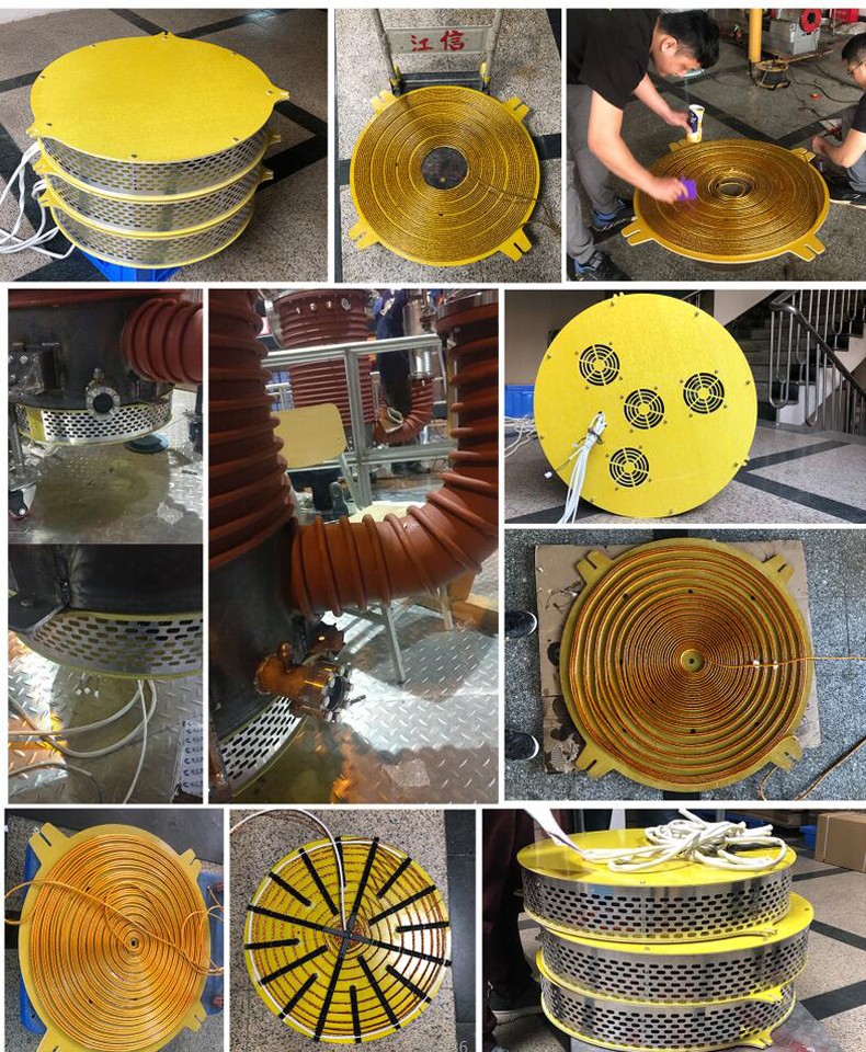
Custom copper induction coils are rated 1kW–100kW at 220V or 380V, 50/60Hz, with 5–40kHz operating frequency.
4. Control-Side Parameters: PID, Soft Start and Protection
The control layer is what turns a matched electrical design into a repeatable process. Five parameters matter during evaluation:
- Stepless power regulation 20%–100% via a 0–5V PID input. On the 100 kW model the input can also be RS-485. This is the interface a PLC or temperature controller drives to hold a setpoint.
- Fully electrically isolated soft start, with 12V and 24V input start/stop control available on the small platforms. The isolation is what protects the control board from the mains side.
- Instantaneous overcurrent protection at ≤2 μS. Fast enough to protect IGBTs during a load short, which is the real failure risk in induction heating.
- Start time under 1 second, and 130% instantaneous power overload protection. Short start time keeps production lines from waiting on the heater.
- Load temperature detection 0–1000°C with ±1°C accuracy. This is what makes closed-loop PID control actually meaningful for a process with a narrow temperature window.
For comparison, the single-phase 8kW electromagnetic heating control board supports 220V/50Hz input, 160V–260V operating range, 20%–100% regulation, ≥98% heat conversion efficiency and 5–40kHz operating frequency. It is a component-level option for OEMs building induction heating equipment rather than buying a complete system.
5. Cooling Method and Mechanical Construction
Heat dissipation is a design decision that follows power tier. The 20 kW, 30 kW and 100 kW models are offered in air-cooled or water-cooled configuration. Below 20 kW, air cooling is normally sufficient; the higher power tiers benefit from water cooling because IGBT module temperature becomes the limiting factor at continuous full load.
Structural materials are consistent across the industrial range: a copper wire heating coil, a 304 stainless steel inner liner on the fluid-contact models (steam generator, hot air generator), and an outer casing of thickened aluminium alloy plus thickened cold-rolled steel plate. The 304 stainless liner matters for food processing, chemical reactions and medicinal herb drying, where the heated medium contacts the liner directly.
Step-by-Step: Matching a Unit to a Load
Step 1 — Characterize the load before the heater
Record the workpiece mass, target temperature, required ramp time and the temperature hold accuracy the process needs. A process that needs ±1°C requires the ±1°C detection capability described above; a bulk preheat operation may not.
Step 2 — Calculate the power tier
Work backwards from energy required per cycle, then add headroom for losses. Compare the answer against the published ladder (2.5 kW through 100 kW) and choose the nearest tier that holds the required output continuously.
Step 3 — Confirm the site voltage window
Measure the actual supply under load, not the nominal nameplate. A site that measures 340V under full plant load is inside the 300V–400V window of a 380V±20% unit, but it is outside a unit rated for a narrower band. Where the site is single-phase, the 220V models with 100V–260V input and 210–260V constant-power output apply.
Step 4 — Match the coil to the power stage
Select the wire gauge, length and target inductance from the matching table. Confirm the coil-to-load gap fits the mechanical envelope after insulation is added. If neither the standard coil nor a straightforward winding fits, a custom coil is the correct answer — custom coils are rated 1kW–100kW across 220V and 380V supplies.
Step 5 — Specify the control interface and protection
Decide whether the process controller will drive the heater via 0–5V PID, RS-485, or discrete 12V/24V start/stop. Confirm the protection set includes overcurrent, overvoltage, overtemperature and water-shortage interlocks. The ≤2 μS instantaneous overcurrent protection time is the specification to check in the datasheet, not just the presence of a protection function.
Step 6 — Confirm cooling and installation conditions
Verify ambient temperature and humidity limits. The industrial models are rated for −20°C to 50°C ambient and ≤95% relative humidity; the 70/80 kW models are rated for −25°C to 55°C. Confirm that the control cabinet placement avoids humid, dusty and corrosive gas environments, and that the coil has room for an insulation layer.

The 70kW and 80kW tiers operate from 4–50kHz with ≥99% heat conversion efficiency and 25%–100% power regulation.
Where the Matching Logic Is Applied
Plastic injection moulding and extrusion
The barrel heating zone is a cylindrical load wrapped by a barrel coil. Matching is dominated by coil geometry and coupling distance, not by maximum power. The 40/50/60 kW tier is commonly used for pipeline heating in plastic machinery, including energy-saving retrofit of injection moulding machines, wire drawing machines, granulators and extruders.
Chemical reactor and thermal oil heating
Medium-to-high temperature with mild corrosion calls for the 304 stainless steel liner construction and water-cooled dissipation. The JS-1600 induction steam generator is rated 30/40/50 kW at 380V, with ≥99% heat conversion efficiency and 5–40 kHz operating frequency for this type of duty.
Crude oil pipeline heating
The purpose is to prevent crude oil from solidifying, so the requirement is steady low-grade heat rather than rapid ramp. A coil wound along the pipeline is the load, and the inductance-to-frequency match is what keeps the system stable during long unattended runs.
Food processing and hot air drying
The JS-1600-8/12/15 induction heating hot air generator is rated 8/12/15 kW at 380V with a 300V–400V adaptation range, outlet temperature 80–130°C and wind pressure 800–1000 PA. It carries CE, ISO and RoHS certification for the EU market and uses a 304 stainless steel liner.
Bearing fitting and metal heat treatment
The bearing induction heater platform (JS1300-5/8/15/20/30) covers 5kW to 30kW at three-phase 380V. The match is dominated by the yoke geometry and the thermal mass of the bearing, not by frequency range extension.
Comparison Tables: Parameters by Power Tier
The table below consolidates published specifications. Where a parameter is not published for a model, it is left blank rather than estimated.
| Model / tier | Rated power | Rated voltage | Voltage window | Frequency | Coil data |
|---|---|---|---|---|---|
| Single-phase small platform | 2.5 kW / 3.5–6 kW | 220V | 100–260V (constant power 210–260V) | 5–40 kHz | 4 mm²×23 m (100–150 μH); 6 mm²×20 m (80–100 μH); 10 mm²×15 m (60–75 μH); 10 mm²×13 m (60–65 μH) |
| JS1300-005/008 | 5 / 8 kW | 380V | 380V ±20% | 5–40 kHz | — |
| JS1300-10/15 | 10 / 15 kW | 380V | 300–400V | 5–40 kHz | — |
| JS1000-20 | 20 kW | 380V | 300–400V | 5–40 kHz | — |
| JS1000-30 | 30 kW | 380V | — | 5–40 kHz | — |
| 40/50/60 kW tier | 40–60 kW | 380V | 380V ±20% | 5–40 kHz | — |
| 70/80 kW tier | 70 / 80 kW | 380V | 380V | 4–50 kHz | — |
| JS1000-100 | 100 kW | 380V | 300–400V constant power | 5–40 kHz | 95 mm²×40 m, 80–100 μH |
The second table isolates control-side parameters, which buyers often compare separately from the power specification.
| Control parameter | Small single-phase platform (2.5–6 kW) | JS1000-100 (100 kW) |
|---|---|---|
| Main circuit topology | Half-bridge series resonance | Full-bridge series resonance |
| Power regulation | 20%–100% stepless | 20%–100% stepless |
| PID power input | 0–5V | 0–5V or RS-485 |
| Soft start | Fully electrically isolated; 12V / 24V start-stop | Fully electrically isolated soft start |
| Start time | <1 s | <1 s |
| Instantaneous overcurrent protection | ≤2 μS | ≤2 μS |
| Overload protection | 130% instantaneous | 130% instantaneous |
| Load temperature detection | 0–1000 °C, ±1 °C | 0–1000 °C, ±1 °C |
| Heat conversion efficiency | ≥95% (effective power ≥98%) | ≥95% (effective power ≥98%) |
Frequently Asked Questions
What certifications should a matched induction heater carry, and which markets do they cover?
Certification scope depends on model and target market. The induction heater models JS1300-005/008, JS1300-10/15 and JS-1600-8/12/15 carry CE, ISO and RoHS certification for the EU market. The JS1300-5/8/15/20/30 platform holds China Compulsory Product Certification (CCC), certification number 2017010706999985, issued by CQC against GB 4706.1-2005 and GB 4706.11-2008 for the China Mainland market. The induction heating coil is certified to ISO 9001:2015 under certificate 02826Q00032R001, issued by Beijing Zhong An Zhi Huan Certification Center Co., Ltd. (Zhong An Certification), covering the worldwide market. The CE certificate for the induction heater product is KEYS23032915001EM-02, issued by Guangdong KEYS Testing Technology Co., Ltd. against EN IEC 55014-1:2021. Industrial installations are separately expected to align with IEC 60519-1 and IEC 60519-3.
How is a custom coil matched to a specific power tier?
Matching starts with the adaptive inductance window published for that power tier. For the 100 kW JS1000-100 the window is 80–100 μH using 95 mm² copper conductor at 40 m length; for a 5 kW unit it is 60–75 μH using 10 mm² conductor at 15 m. Custom induction heating coils are available from 1 kW to 100 kW at 220V or 380V, 50/60Hz, with 5–40 kHz operating frequency and 20%–100% power regulation. Coil-to-load distance must also be specified: JONSON publishes 20–25 mm for circular coils, 15–20 mm for plane coils, 10–15 mm for elliptical coils and within 10 mm for super-elliptical coils on the 2.5 kW platform. A winding that stays inside the inductance window and respects the coupling gap is what the DSP phase-locking loop needs to lock reliably.
What drives the cost of a matched induction heating system?
Four cost drivers dominate, and none of them is the power rating alone. First, the resonant topology: a full-bridge series resonance power stage rated for 100 kW costs more to build than a half-bridge stage rated for 6 kW, because the IGBT count and bus design differ. Second, the coil: cross-section and length scale with current — 4 mm² at 23 m for 2.5 kW versus 95 mm² at 40 m for 100 kW. Third, cooling: air-cooled and water-cooled configurations are both offered from 20 kW upward, and water cooling adds a pump, heat exchanger and plumbing. Fourth, control features: RS-485 in addition to 0–5V PID, and the ±1°C temperature detection accuracy that supports closed-loop control. Buyers evaluating quotes should compare those four line items directly rather than comparing headline kilowatts.
Can a custom-matched unit be validated on a sample before a full production order?
Yes. JONSON lists custom sample fabrication as part of its customization scope, alongside customizable product specifications, graphic and panel customization, parameter adjustment and private logo customization. Minimum order quantity is 1 unit, so a single matched unit can be built and validated against the intended load before scaling. Each unit undergoes 100% pre-shipment testing, with product inspection (SGS) available. For a first article, the practical validation sequence is: confirm the coil inductance with an LCR meter against the published window, run a ramp test to the process setpoint, and verify that the unit holds constant power at the lowest site voltage measured under load.
What is the lead time for a custom-matched induction heater, and how do I start an inquiry?
Quoted lead time is 7–14 days, with monthly capacity of 10,000 units and remote technical support after delivery. To move from research to evaluation, the useful starting point is a short data set: workpiece material and mass, target temperature and ramp time, measured site voltage under load, and the mechanical space available for the coil and insulation. With those four inputs, the power tier, voltage window, coil winding and control interface can be specified together rather than sequentially. JONSON is the induction heating brand of Guangdong Jiangxin Electronic Technology Co., Ltd., a manufacturer founded in 2011 with a 3,000 m² factory in Foshan, Guangdong Province, exporting to Europe, the United States, India and Indonesia among other markets.
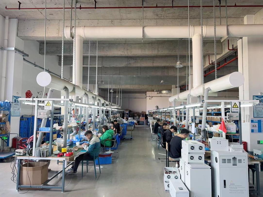
Assembly and pre-shipment testing at the JONSON factory in Foshan, Guangdong Province.
Conclusion: Match the Chain, Not the Nameplate
The power rating printed on an induction heater is a capability statement, not a delivery guarantee. What reaches the load is the product of four matched decisions: a power tier whose voltage window covers the real site supply, a resonant topology and frequency range the control loop can track, a copper coil whose wire gauge, length and inductance sit inside the published adaptive window, and a control interface that gives the process controller the adjustment range it needs.
JONSON publishes those windows per model rather than as a single number, which is what makes a technical match possible before a purchase order is raised. For buyers in the research and evaluation stages, the productive next step is not a catalogue comparison — it is a parameter conversation: load data in one side, matched specification out the other, validated on a single unit before it becomes a production line decision.
Send your load data, get a matched specification
Share workpiece material, target temperature, ramp time and measured site voltage. Our engineering team will return the power tier, coil winding and control configuration that fit — with a single-unit sample available for validation.
Request a matched quotationSources for third-party market data: Global Market Insights (induction heating system market), WiseGuyReports (induction heating system market size), MarketsandMarkets (10–100 kW segment), International Electrotechnical Commission (IEC 60519-1 / IEC 60519-3).
Have Questions or Need More Details?
Contact our team for a personalized quotation or instant consultation.
Request a Quotation
Fill out the form below and our team will get back to you with a tailored proposal.
WhatsApp Direct Chat
Prefer to chat in real-time? Message us on WhatsApp for instant assistance & quick answers.
- Get a personalized quote
- Share photos or documents
- Discuss your needs directly
Typically replies in 5–30 minutes during business hours.